Magnetic Motorways (Final Post on this)
Welcome back guys!
I feel obligated to check that all of you are okay, especially as we are in quarantine. I really hope all of you are okay at the moment, and are looking after yourselves and each other as best as you can.
I am back with another post about magnetic motorways, and my last one on this actually. As I always say, if this is the first time you are reading this series, I am talking about a theoretical idea in which we could make cars that levitate and move using magnetic forces. To understand this, it is probably better you start with some of my earlier posts:
First Post
Second Post
Last Post
And if you've been keeping up then you know what I'm talking about. In the last post I talked about how I am going to add the magnetic shielding so the magnetic fields are not dangerously strong around the car and inside the car. The following drawing has this, and shows the general design of the car as well. I take into account that my handwriting is very hard to decipher, so I am going to explain what is written in the pictures below.
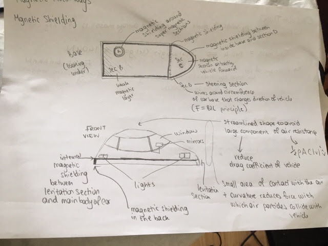
I get feedback that some of what is described is hard to understand so I will try to simplify it so it can be understood while being as informative as possible. The image at the top gives the view from looking underneath the vehicle. There will be magnetic shielding in a thick circle around section A, which is the most heavily magnetised part that enables stability in levitation (think of it like the four legs of a chair) I have only drawn one of the circles, but in reality, there would be six of them evenly distributed across the base. There will be magnetic shielding around the main base (Section B) which is the magnetic base that repels the floor so the car can levitate. There also needs to be magnetic shielding separating sections B and C. Section C is the part that attracts the vehicle forward, and in previous posts I have shown that the magnetism in this section increases as you get closer to the front of the vehicle (towards the right) so the car is pulled forwards. Section D is the steering section, and actually isn't magnetic, it is a wire wrapped around the edges of the base. Depending on the direction of the current (electron flow) in the wires, the vehicle rotates in that direction. (Physicists, this is the F = BIL principle, since the current is perpendicular to the magnetic field).
The drawing under the top one shows what the car looks like from its outer appearance. The car is streamlined so that air resistance doesn't act against the car too largely, so the car isn't slowed down (I also added a n equation there if you are interested). The curvature of the front of the vehicle gives it a small surface area of contact with the air, so there is reduced air resistance from this too. There are lights, windows and mirrors, and looking at this now, I realise I forgot to draw doors (clap for me!!) but obviously there would be doors too. The levitation section (which is the base of the car) is at the bottom of the vehicle and is seperated from the main body of the car by thick internal magnetic shielding, so the magnetic fields don't interfere with the electronic components inside the body of the car.
The next image shows my calculations for this. The are pretty self explanatory to be honest, but I'l go through them briefly.
 I will explain a couple things. The total MASS is the total of the mass of the two passengers. Straightforward. The WEIGHT is the force that this mass provides, and to get that we multiply the mass (in kg) by g (gravitational field strength i.e. the pull of the earth) to get the force downwards. I add this to the weight of an average vehicle to get the total weight downwards. To levitate in equilibrium vertically (this basically means that the car is not moving up or down as the car is moving, it maintains the same position in the air) the force downwards must be balanced with the force upwards. Therefore, there would have to be a force of (magnetic) repulsion between the road and the car. I originally thought of both of them as bar magnets, but the equation for that is disgusting, not one that I understand or am prepared to explain. It also didn't fully apply to the situation. I've opted instead for the car base and the road to act as magnetic surfaces, and the equation for this is much simpler, and works, provided the volume of the air gap is not large in comparison to the volume of the surfaces, and the area of the magnetic road section is the same as the area of the car base (not the case, but there would be negligible difference). For more information on that equation (if you care) this is the website to go to:
https://en.wikipedia.org/wiki/Force_between_magnets
You may also notice how I said that this is theoretically not possible, and this is due to Earnshaw's Theorem. The following image explains this, and how the design can combat this.

The last thing as promised are the steering controls:

Until then,
EO
I feel obligated to check that all of you are okay, especially as we are in quarantine. I really hope all of you are okay at the moment, and are looking after yourselves and each other as best as you can.
I am back with another post about magnetic motorways, and my last one on this actually. As I always say, if this is the first time you are reading this series, I am talking about a theoretical idea in which we could make cars that levitate and move using magnetic forces. To understand this, it is probably better you start with some of my earlier posts:
First Post
Second Post
Last Post
And if you've been keeping up then you know what I'm talking about. In the last post I talked about how I am going to add the magnetic shielding so the magnetic fields are not dangerously strong around the car and inside the car. The following drawing has this, and shows the general design of the car as well. I take into account that my handwriting is very hard to decipher, so I am going to explain what is written in the pictures below.

I get feedback that some of what is described is hard to understand so I will try to simplify it so it can be understood while being as informative as possible. The image at the top gives the view from looking underneath the vehicle. There will be magnetic shielding in a thick circle around section A, which is the most heavily magnetised part that enables stability in levitation (think of it like the four legs of a chair) I have only drawn one of the circles, but in reality, there would be six of them evenly distributed across the base. There will be magnetic shielding around the main base (Section B) which is the magnetic base that repels the floor so the car can levitate. There also needs to be magnetic shielding separating sections B and C. Section C is the part that attracts the vehicle forward, and in previous posts I have shown that the magnetism in this section increases as you get closer to the front of the vehicle (towards the right) so the car is pulled forwards. Section D is the steering section, and actually isn't magnetic, it is a wire wrapped around the edges of the base. Depending on the direction of the current (electron flow) in the wires, the vehicle rotates in that direction. (Physicists, this is the F = BIL principle, since the current is perpendicular to the magnetic field).
The drawing under the top one shows what the car looks like from its outer appearance. The car is streamlined so that air resistance doesn't act against the car too largely, so the car isn't slowed down (I also added a n equation there if you are interested). The curvature of the front of the vehicle gives it a small surface area of contact with the air, so there is reduced air resistance from this too. There are lights, windows and mirrors, and looking at this now, I realise I forgot to draw doors (clap for me!!) but obviously there would be doors too. The levitation section (which is the base of the car) is at the bottom of the vehicle and is seperated from the main body of the car by thick internal magnetic shielding, so the magnetic fields don't interfere with the electronic components inside the body of the car.
The next image shows my calculations for this. The are pretty self explanatory to be honest, but I'l go through them briefly.

https://en.wikipedia.org/wiki/Force_between_magnets
You may also notice how I said that this is theoretically not possible, and this is due to Earnshaw's Theorem. The following image explains this, and how the design can combat this.

(If you don't care about the equations keep scrolling)
Again, I think this is pretty self explanatory, so I wont do too much talking on this. I will, however, make mention of B, which is a magnetic property (flux density) which increases the force between the two surfaces (Road and car). The equation for this does include current (yup. that letter that looks like an L. That's an I. Yes my handwriting. I'm sorry :/), but it also includes number of coils (the n) so in order for the current to not be too high, having a large number of coils would help too. The magnetic permeability would be increased by using iron for the coils. This means that the overall flux density is great without having to increase the current too much, so resistance and overheating isn't a problem.The last thing as promised are the steering controls:

This does need explaining. The wheel is connected to a bar, which is connected to two curved variable resistors, each in different circuits, and in opposite orientation. The two circuits have current in opposite directions to provide the currents in section D so the vehicle can turn in different directions. When the steering wheel is turned in one direction, the resistance in the circuit for the opposite direction is increased so there is no current in that circuit, while it is increased for the circuit that corresponds for the direction the driver is steering in. This causes the car to turn in the direction that the current flows in, which is the direction the driver turned the steering wheel in.
And that is it! This is my final post on the magnetic motorways. It is an idea I have thoroughly enjoyed exploring, and though there isn't much room for it in reality at the moment, and there is probably a lot more that needs to go into the design so that it works (I haven't thought much about interaction with the road) it has been so fun to research this and design it. But on to the next.
I will return with some coding, so to all my coders, stay tuned. I have almost finished all the code for the Gamekid device, and my newest basketball game is something that I have been working on while researching this. in the next post I will talk about this and how I intend to make it work as a handheld device.
Until then,
EO

Comments
Post a Comment